Difference between revisions of "Shared talk:Group 2"
(Material List) |
|||
| Line 1: | Line 1: | ||
| − | 1. continuous motor x 3 | + | =='''Interactive Guiding Map''' | Anne De Schepper & Shireen Xiaolin Ou== |
| − | 2. wood board x 3 | + | |
| − | 3. arduino uno x 1 | + | |
| − | 4. breadboard x 1 | + | [[File:4s.gif|center|500px|caption]] |
| − | 5. wires | + | |
| + | |||
| + | Group Member: Anne De Schepper & Shireen Xiaolin Ou | ||
| + | |||
| + | Duration: 2 Weeks | ||
| + | |||
| + | Status: Prototype Model Making | ||
| + | |||
| + | |||
| + | |||
| + | =='''What we do?''' | "problem statement"== | ||
| + | |||
| + | [[File:Ao01.gif|center|400px|caption]] | ||
| + | |||
| + | ''What we do?'' | ||
| + | |||
| + | At the entrance of science center, you are usually welcomed by several notice-boards about the location of a room and its events. We want to replace the dull boring boards with an interactive guiding system, where a colored ball would lead you the way to your destination. | ||
| + | |||
| + | For example, a red ball may represent "hyperbody-space"; so if you want to head to "hyperbody-space" yet you don't know the way, you can pick up a red ball and place it at the start of the guiding system. This system would slowly move the ball towards your room. All you need to do is following the track. | ||
| + | |||
| + | The following animation simulates how the system is going to work in the hallway. | ||
| + | |||
| + | [[File:0 (2).JPG|295px]][[File:0 (3).JPG|270px]] | ||
| + | |||
| + | |||
| + | |||
| + | =='''What are the inspirations''' | "previous approaches"== | ||
| + | |||
| + | [[File:2s.gif |center|400px|caption]] | ||
| + | |||
| + | ''What are the inspirations?'' | ||
| + | |||
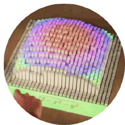
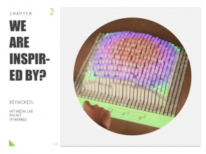
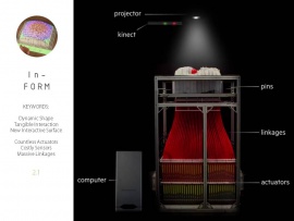
| + | We are inspired by "InForm", an MIT Media Lab project. In this project, they used pins as actuators to control the shape of a surface. However, they do have the drawback of using too many electronic actuators, making massive and redundant linkages. | ||
| + | |||
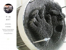
| + | And the simple toy of "spijkerbed" comes to our mind. Only by changing the base environment for the pin art, we can achieve a variety of effects. Is it possible we can make use of this simple mechanism? The answer is a definite yes. | ||
| + | |||
| + | [[File:0 (4).JPG|295px]][[File:0 (5).JPG|270px]][[File:0 (6).JPG|270px]] | ||
| + | |||
| + | |||
| + | =='''How It Works''' | "machanism design"== | ||
| + | |||
| + | [[File:3s.gif |center|400px|caption]] | ||
| + | |||
| + | ''How It Works?'' | ||
| + | |||
| + | First, we change the shape of supporters of the pins, to change the shape of pin surface. For the supporters, we use X-Y coordinates to control its movement. In order to quantify the movement, we use a stick with spiral screws. By rotating the stick we can transform a motor into a linear actuator. | ||
| + | |||
| + | [[File:0 (7).JPG|295px]][[File:0 (8).JPG|270px]][[File:0 (9).JPG|270px]] | ||
| + | |||
| + | |||
| + | =='''Prototype Making''' | "model making"== | ||
| + | |||
| + | [[File:5s.gif |center|400px|caption]] | ||
| + | |||
| + | ''Finally, our design'' | ||
| + | |||
| + | Our design consists of 3 parts. The TOP part is made of: a metal pins’ surface, a height control stopper, and bottom caps. The BOTTOM part consists of 3 driving engines(motors), a “weird shape” affecting the pin surface, and the supporting structure. Another side box is attached to the main body of the design as well, where arduino and all wires are hidden. | ||
| + | |||
| + | |||
| + | [[File:0 (10).JPG|295px]][[File:0 (11).JPG|270px]][[File:0 (12).JPG|270px]] | ||
| + | |||
| + | |||
| + | =='''Videos''' == | ||
| + | |||
| + | video video video | ||
| + | |||
| + | =='''List of Material Used''' == | ||
| + | * 1. continuous motor x 3 | ||
| + | * 2. wood board x 3 | ||
| + | * 3. arduino uno x 1 | ||
| + | * 4. breadboard x 1 | ||
| + | * 5. wires | ||
Revision as of 00:36, 19 April 2017
Contents
Interactive Guiding Map | Anne De Schepper & Shireen Xiaolin Ou
Group Member: Anne De Schepper & Shireen Xiaolin Ou
Duration: 2 Weeks
Status: Prototype Model Making
What we do? | "problem statement"
What we do?
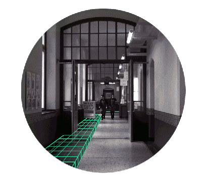
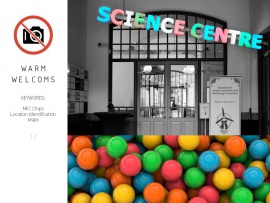
At the entrance of science center, you are usually welcomed by several notice-boards about the location of a room and its events. We want to replace the dull boring boards with an interactive guiding system, where a colored ball would lead you the way to your destination.
For example, a red ball may represent "hyperbody-space"; so if you want to head to "hyperbody-space" yet you don't know the way, you can pick up a red ball and place it at the start of the guiding system. This system would slowly move the ball towards your room. All you need to do is following the track.
The following animation simulates how the system is going to work in the hallway.
What are the inspirations | "previous approaches"
What are the inspirations?
We are inspired by "InForm", an MIT Media Lab project. In this project, they used pins as actuators to control the shape of a surface. However, they do have the drawback of using too many electronic actuators, making massive and redundant linkages.
And the simple toy of "spijkerbed" comes to our mind. Only by changing the base environment for the pin art, we can achieve a variety of effects. Is it possible we can make use of this simple mechanism? The answer is a definite yes.
How It Works | "machanism design"
How It Works?
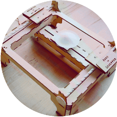
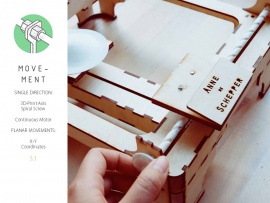
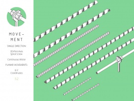
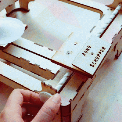
First, we change the shape of supporters of the pins, to change the shape of pin surface. For the supporters, we use X-Y coordinates to control its movement. In order to quantify the movement, we use a stick with spiral screws. By rotating the stick we can transform a motor into a linear actuator.
Prototype Making | "model making"
Finally, our design
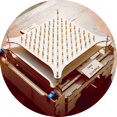
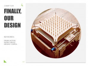
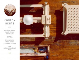
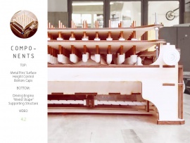
Our design consists of 3 parts. The TOP part is made of: a metal pins’ surface, a height control stopper, and bottom caps. The BOTTOM part consists of 3 driving engines(motors), a “weird shape” affecting the pin surface, and the supporting structure. Another side box is attached to the main body of the design as well, where arduino and all wires are hidden.
Videos
video video video
List of Material Used
- 1. continuous motor x 3
- 2. wood board x 3
- 3. arduino uno x 1
- 4. breadboard x 1
- 5. wires
