Difference between revisions of "Shared:Group 1"
| Line 196: | Line 196: | ||
| − | <youtube width="850" height="400"> | + | <youtube width="850" height="400">vy1_t6OOqYE</youtube>syntax |
Revision as of 21:52, 6 July 2017
Contents
Stepper motor tutorial: making quarter turns and back
This tutorial is about a stepper motor than can make a quarter turn and goes back.
It can do this multiple times.
Parse the amount of cycles in the Serial Monitor!
Needed:
wires (catagorized in color preferably) breadboard
L239d H-bridge (scheme: [1]) 28BYJ-48 Stepper motor
Setup:
1. Place the bridge (note the little dot)
2. Connect the supply wires and ground wire
3. Connect the output wires (here it is 9, 10, 11 and 12)
4. Connect the wires for the stepper motor
Code: [2]
Inspiration and References
Our first discussion about the design took place on wednesday where we discussed our ideas for the installation, and the later developments have been discussed with the tutors today, all the ideas which we are taking forward are listed below.
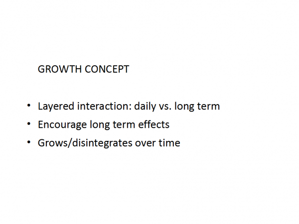
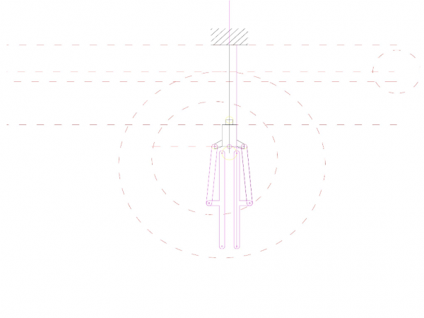
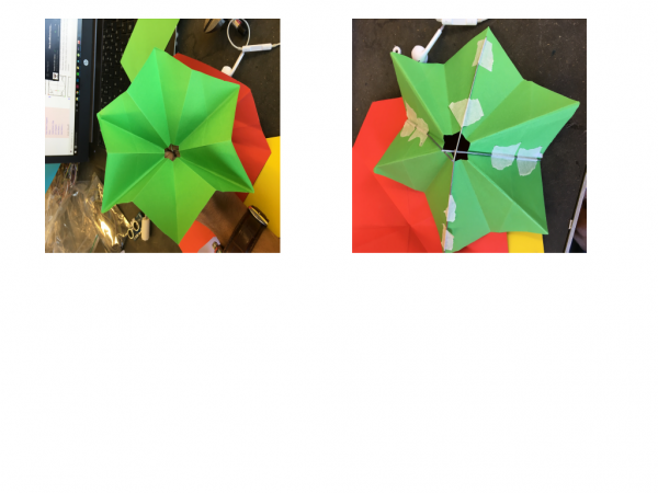
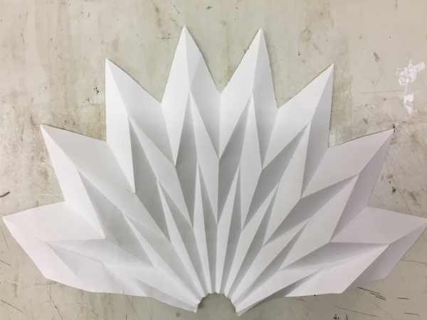
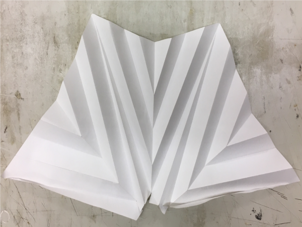
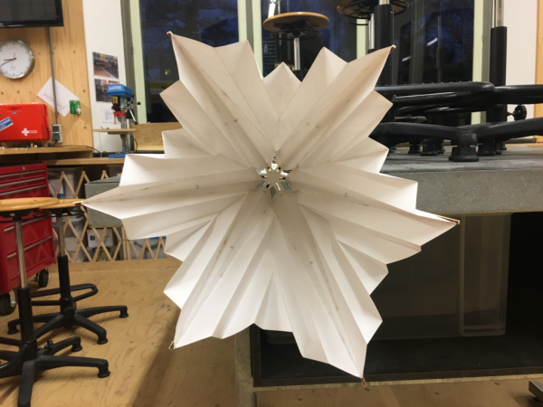
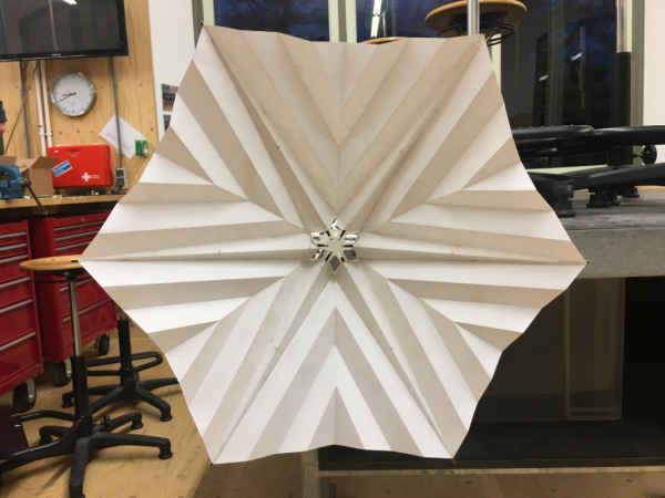
Ideas: 1. The installation is imagined to be similar in character to an animal in the wild, where during a safari, the people are expected to maintain absolute silence to see the creature be active in its natural environment. 2. The idea of growth, such that the installation is a constantly growing piece, with 2 layers of movements, the first being a short cycle of interactive movement, where the physical interaction with people, in this case the noise created, activates the pods in the installation to open, thus diffusing and absorbing the noise. The form of each of the components of the installation, is origami based with design influences directly from natural elements, like flowers and birds. 3. Another layer of intervention is the fusion of the movement of the structure with certain sounds, either natural or instrumental, this idea is still to be thought over, but most probably it will be a concept on paper and not in the physical application.
Please find below, some links of videos which we referred to for inspiration.
[3]
[4]
[5]
Servo motor tutorial
You can use this tutorial to control the angles of the Servo engine in a reliable way.
Needed:
Arduino, wires, MG946R motor, 6V Power Adapter
Setup:
1. Connect the wires to the Arduino (Supply (red): VIN, Ground (brown): GnD, Signal (orange): pick a PMW port (this example: 3) )
2. Plug in the 6V Power Adapter to the Arduino
3. Test how many degrees the range of the Servo motor 'overreaches' a clean 180 degree turn
4. Upload this code from the IDE, and adjust the value for 'overreach':
/*
Arduino Servo Test sketch
edits by Jorik van den Bos
*/
#include <VarSpeedServo.h>
VarSpeedServo servoMain; //define our Servo
int servospeed = 26;
int angle = 0;

//in this example, the Servo is connected to port 3
void setup()
  {
   Serial.begin(9600);
   servoMain.attach(3); // servo on digital pin 10
  }

//in the Serial Monitor you can parse the desired angle (0 - 180)
void loop()
  {
  if (Serial.available())
    {
     angle = Serial.parseInt();
     servoMain.slowmove(toAngle(angle), servospeed );
    }
  }

//function toAngle will return a mapped angle, so that the code can correspond with the real range of the Servo motor
//change the value for 'overreach' to the amount of angles that the Servo's is bigger (negative for smaller) than 180
int toAngle(int inp)
  {
   int overreach = 15;
   return overreach + map( inp,0,180,0,180 - overreach);
  }
Presentation 4/5/2017
Materials and items
Used:
Lotus Arduino x 1 Black Arduino Uno x 1 300 x 600 x 3 triplex x 2 Breadboard x 2 Transluscent plastic sheet x 1 Stepper motor 28byj-48 x 1 Loudness sensor x 1 Servo motor mg946r x 1 Adapter 6V x 1 Breadboard x 2 Grove wires x 3 Jumper wires x plenty USB cables x 2
Needed:
High accuracy loudness sensor x 1 Servo motor mg946r x 1
Prototype Arduino codes
/*
Arduino Servo Test sketch
edits by Jorik van den Bos
*/
#include <VarSpeedServo.h>
VarSpeedServo servoMain; //define our Servo
int servospeed = 10;
int angle = 0;
int stepcount = 0;
//int start = toAngle(0);


//loudness
int val = 0;

//in this example, the Servo is connected to port 3
void setup()
  {
   Serial.begin(9600);
   servoMain.attach(3); // servo on digital pin 10
  }

//in the Serial Monitor you can parse the desired angle (0 - 180)
void loop()
  {
//   if (stepcount < 5001) stepcount++;
//   if (stepcount<10) servoMain.slowmove(toAngle(0), servospeed );
//  //loudness
//  val = analogRead(0);
//  Serial.println(val);

//  if (val>400 && stepcount > 5000)
//    {
//     angle = 0;
//     servoMain.slowmove(toAngle(angle), servospeed );
//    }

    if (Serial.available())
    {
     angle = Serial.parseInt();
     servoMain.slowmove(toAngle(angle), servospeed );
    }
  }

//function toAngle will return a mapped angle, so that the code can correspond with the real range of the Servo motor
//change the value for 'overreach' to the amount of angles that the Servo's is bigger (negative for smaller) than 180
int toAngle(int inp)
  {
   int tweak = 0;
   int overreach = 15
   ;
   return tweak + overreach + map( inp,0,180,0,180 - overreach);
  }

